
Lesson 2 of 6
The RC Low Pass Filter
In the previous lesson, we saw that a resistor and a capacitor smooth out fast changes. Audio is just a voltage that changes fast. So, if we feed audio into the same circuit, the high frequencies get smoothed out (removed) while the low frequencies pass through.
1. Building the Filter
Here's the RC low pass filter:
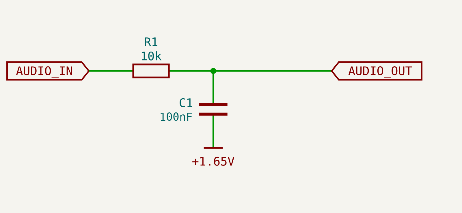
It's the same circuit as before. There are only two changes:
- The input is now audio (use the 16bit's A1 output).
- The capacitor is connected to 1.65V (our virtual ground rail) instead of 0V.
- We use a 104 (100nF) capacitor.
💡 For a low pass filter, connecting the capacitor to 0V or 1.65V gives you the same result. The capacitor only cares about changes (and audio is all about changes). But using the virtual ground keeps everything referenced to the middle of our signal. You will see why this matters in the next lesson.
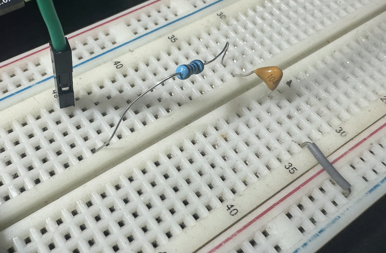
Now, connect the scope:
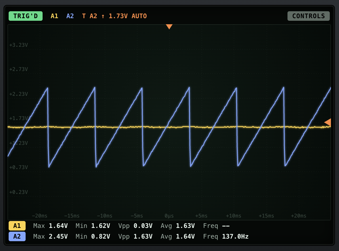
- Connect the audio input to the 16bit's A2 input. This is the original waveform (blue).
- Connect the filter output to the 16bit's A1 input through the buffered oscilloscope probe. This is the filtered waveform (yellow).
Connect the filter output to the line out as well and listen while you look at the scope.
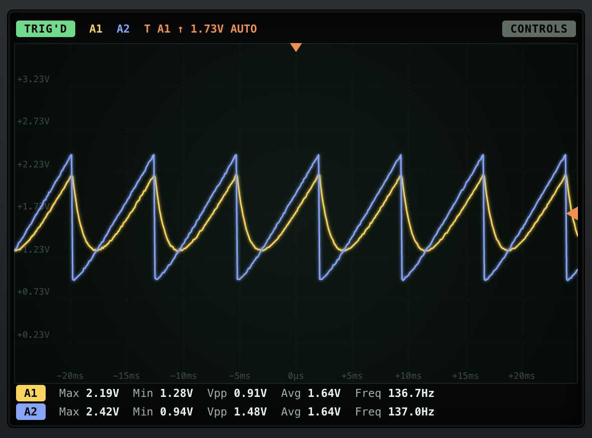
The sharp edge of the sawtooth gets rounded. Those sharp edges are where the high frequencies live, and that's what the filter removes.
👂 Listen to it. The sound is darker and softer than the raw sawtooth.
2. Cutoff Frequency
Every RC filter has a cutoff frequency (fc). Frequencies below it pass through, and frequencies above it get reduced. Here's how to calculate it:
fc = 1 / (2 × π × R × C)
For 10k and 100nF:
fc = 1 / (2 × 3.14 × 10,000 × 0.0000001) ≈ 160Hz
Our sawtooth is about 137Hz, which is right around the cutoff frequency. That's why the output is still a sawtooth, just smaller and rounder.
💡 Here's a shortcut: with a 100nF capacitor,
- 1k → ~1.6kHz
- 10k → ~160Hz
- 100k → ~16Hz
- 1M → ~1.6Hz (almost nothing gets through)
Every time you make R (or C) 10X bigger, the cutoff frequency gets 10X lower.
🛠 Try 1k, 100k and 1M resistors and listen to each of them.
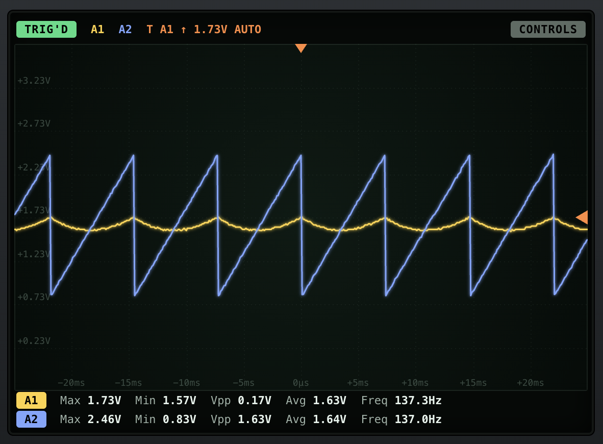
Now, go back to the 10k resistor and slowly increase the frequency of the sawtooth.
3. It's Not a Brick Wall
The cutoff frequency is not a hard line. Frequencies above fc are not completely removed. They are reduced gradually:
- At fc, the signal is reduced to about 70% (that's -3dB).
- For every octave (2X the frequency) above fc, the signal is halved (-6dB).
We call this a first-order or 6dB/octave filter. It's a gentle filter. That's why the 100k version still sounds like a sawtooth, just quieter and duller.
💡 In the 4th lesson, we will make this filter steeper by stacking two of them. That's exactly what the LOW module does.
4. Input & Output Impedance
Our RC filter is just a resistor followed by a capacitor. So, we can reuse what we learned about impedance:
- Output impedance is about R. With 100k, the output impedance is 100k. If you connect it directly to anything (like the line out or the 16bit A1 probe), it will get loaded.
- Input impedance is at least R. With 1k, the filter loads the source a lot (remember, every Bread Modular output already has a 1k resistor in series).
This is why we always put a buffer after an RC filter. It gives us high input impedance (so it won't load the capacitor) and 0 ohms output impedance (so the filter can drive anything).
🛠 Remove the buffer from the oscilloscope probe and connect the filter output directly to the 16bit A1. Try it with the 100k resistor. Can you see the difference?