
Lesson 3 of 6
The RC High Pass Filter
What if we swap the resistor and the capacitor? We get the opposite: a high pass filter. High frequencies pass through and low frequencies are reduced.
We don't use a high pass filter in the LOW module. But it shows up in almost every audio circuit (usually without anyone noticing), so it's worth understanding.
1. Building the Filter
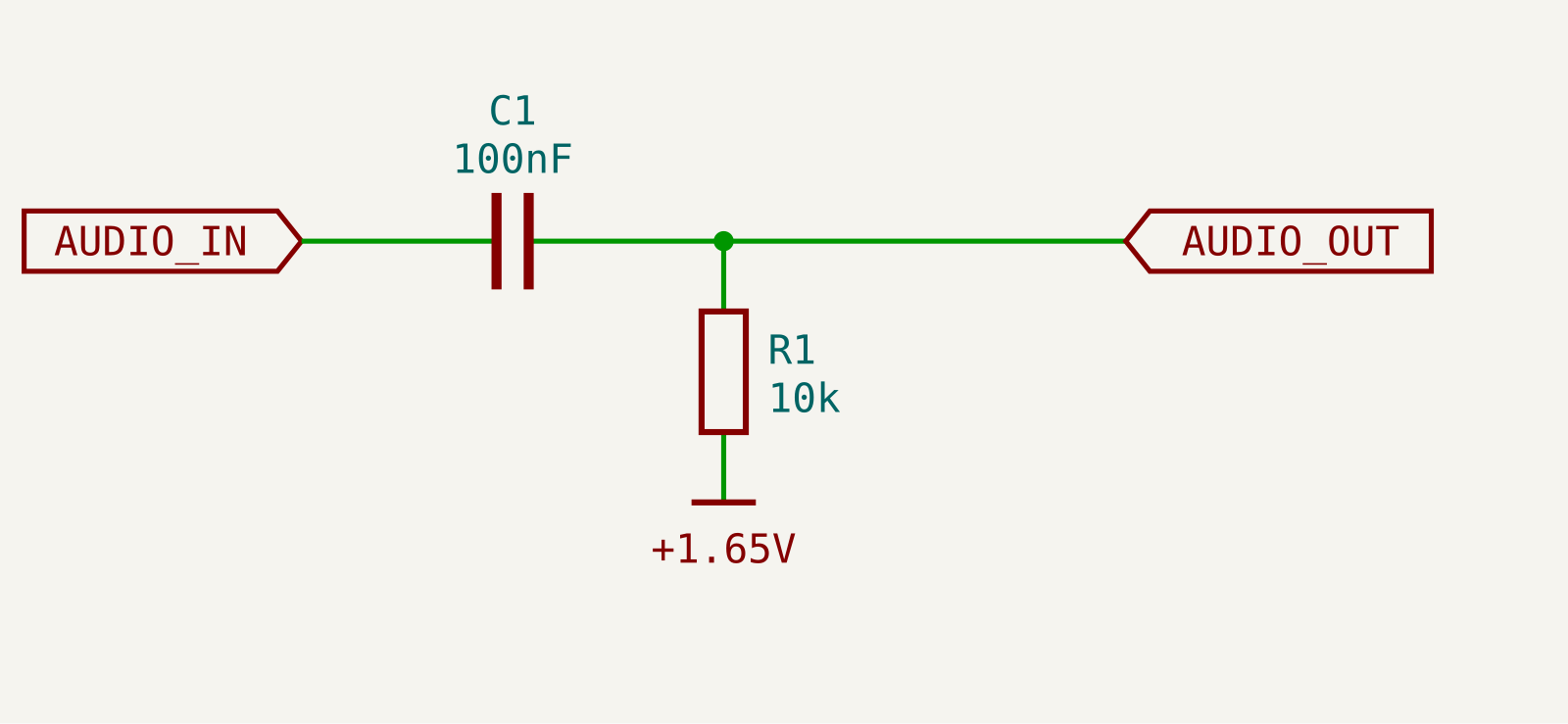
- The cutoff frequency formula is exactly the same:
fc = 1 / (2 × π × R × C) - With 10k and 100nF, it's about 160Hz.
Build it on the breadboard the same way as the low pass filter, just with the resistor and the capacitor swapped. The capacitor sits in the audio path, and the resistor goes to the 1.65V rail.
Connect the scope just like in the previous lesson:
- The audio input goes to the 16bit's A2 input (blue).
- The filter output goes to the 16bit's A1 input through the buffered oscilloscope probe (yellow).
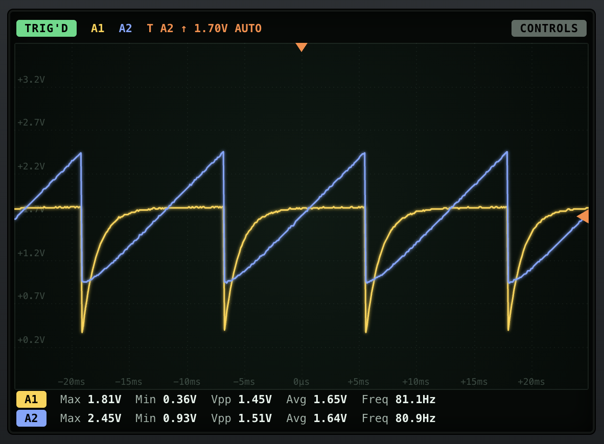
Our sawtooth is below the cutoff frequency, so the slow ramp mostly gets removed. Only the sharp edge passes through as a spike, and the output quickly settles back to 1.65V.
👂 Listen to it. It's thinner. You lose the body of the sound, but the buzz stays.
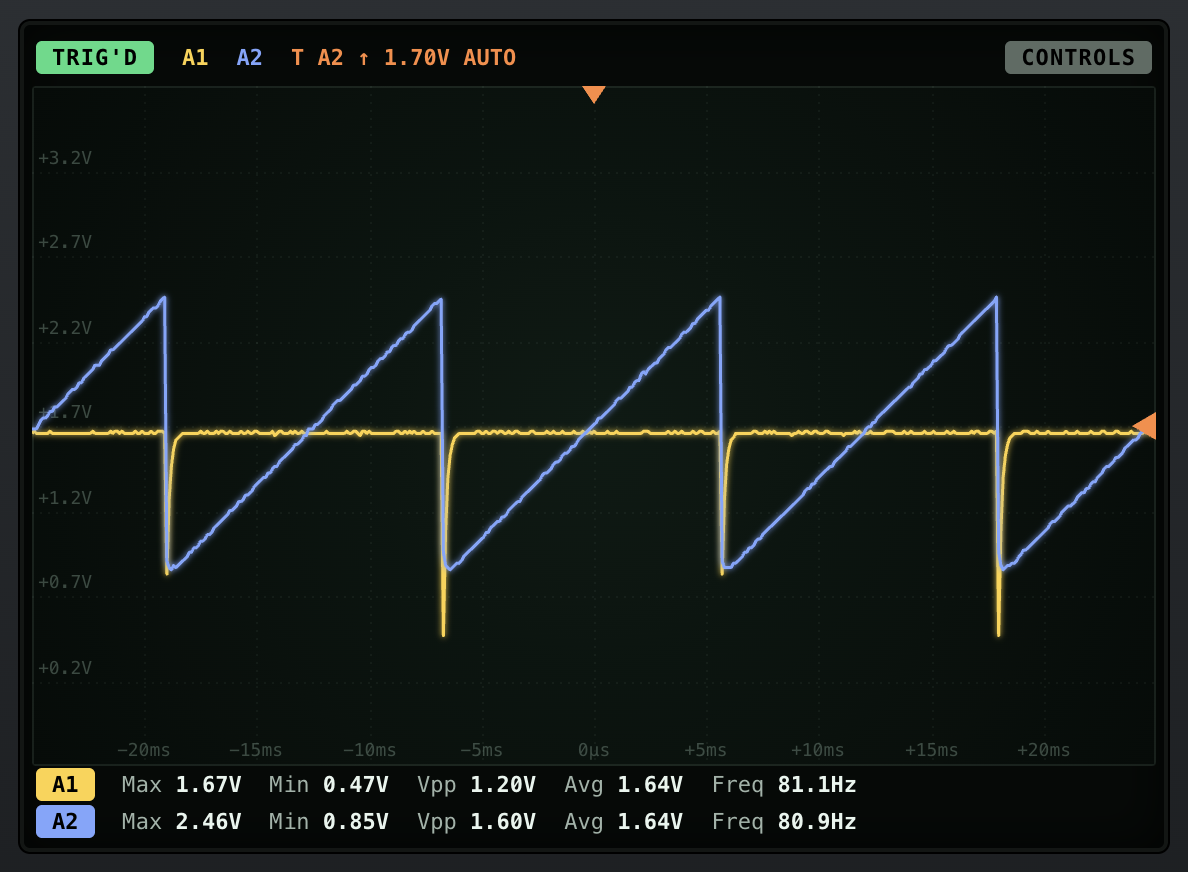
🛠 Now use a 10nF capacitor (fc ≈ 1.6kHz). The spikes get even narrower and it sounds very thin.
2. Why the Resistor Goes to 1.65V
Now, go back to the 100nF capacitor, connect the resistor to 0V instead of the 1.65V rail, and check the output.
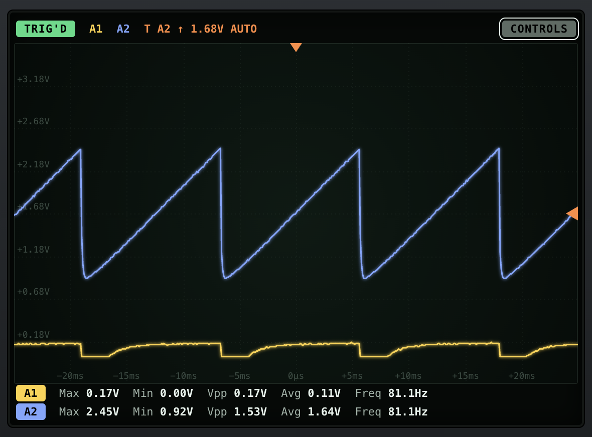
A capacitor blocks DC (any voltage that doesn't change). It only lets the changes through. So the output has no idea where the original midpoint was. The resistor decides it:
- If the resistor goes to 0V, the waveform wiggles around 0V.
- If the resistor goes to 1.65V, the waveform wiggles around 1.65V.
In our setup, nothing can go below 0V. So we lose half of the waveform. That's why we use the virtual ground.
3. DC Blocking
That "blocks DC" feature is very useful. It's called AC coupling, and the capacitor is called a coupling capacitor (or a DC-blocking capacitor).
- Your computer's audio output and our line in/out modules use coupling capacitors to connect systems that use different midpoints (0V vs 1.65V).
- A very low cutoff frequency (like 20Hz or lower) is used for this, so we don't hear any filtering.
💡 Remember the potentiometer experiment in the previous course? The midpoint of the waveform moved as we turned the knob, and we said the line out corrects it. Now you know how: it's a coupling capacitor.
🛠 Use a 100nF capacitor (104) with a 100k resistor (fc ≈ 16Hz). Feed it the output of the potentiometer experiment and turn the knob. The midpoint now stays at 1.65V.