
Lesson 1 of 6
Capacitors
To build a filter, we need a new component: the capacitor. Resistors and capacitors together are the core of almost every analog filter, including the one inside our LOW module.
0. What is a Capacitor?
A capacitor stores charge. Think of it as a tiny, very fast rechargeable battery.
- We measure capacitance in farads (F).
- One farad is huge, so in audio circuits we use much smaller units:
- 1µF (microfarad) = 1,000nF
- 1nF (nanofarad) = 1,000pF (picofarads)
- The higher the value, the more charge it can hold (and the longer it takes to fill up).
Reading Capacitor Codes
Small ceramic capacitors usually have a 3-digit code printed on them. The first two digits are the value, and the third digit is the number of zeros. The result is in picofarads.
- 102 → 10 + 00 → 1,000pF = 1nF
- 103 → 10 + 000 → 10,000pF = 10nF
- 104 → 10 + 0000 → 100,000pF = 100nF
These three are the ones we use the most in this course.
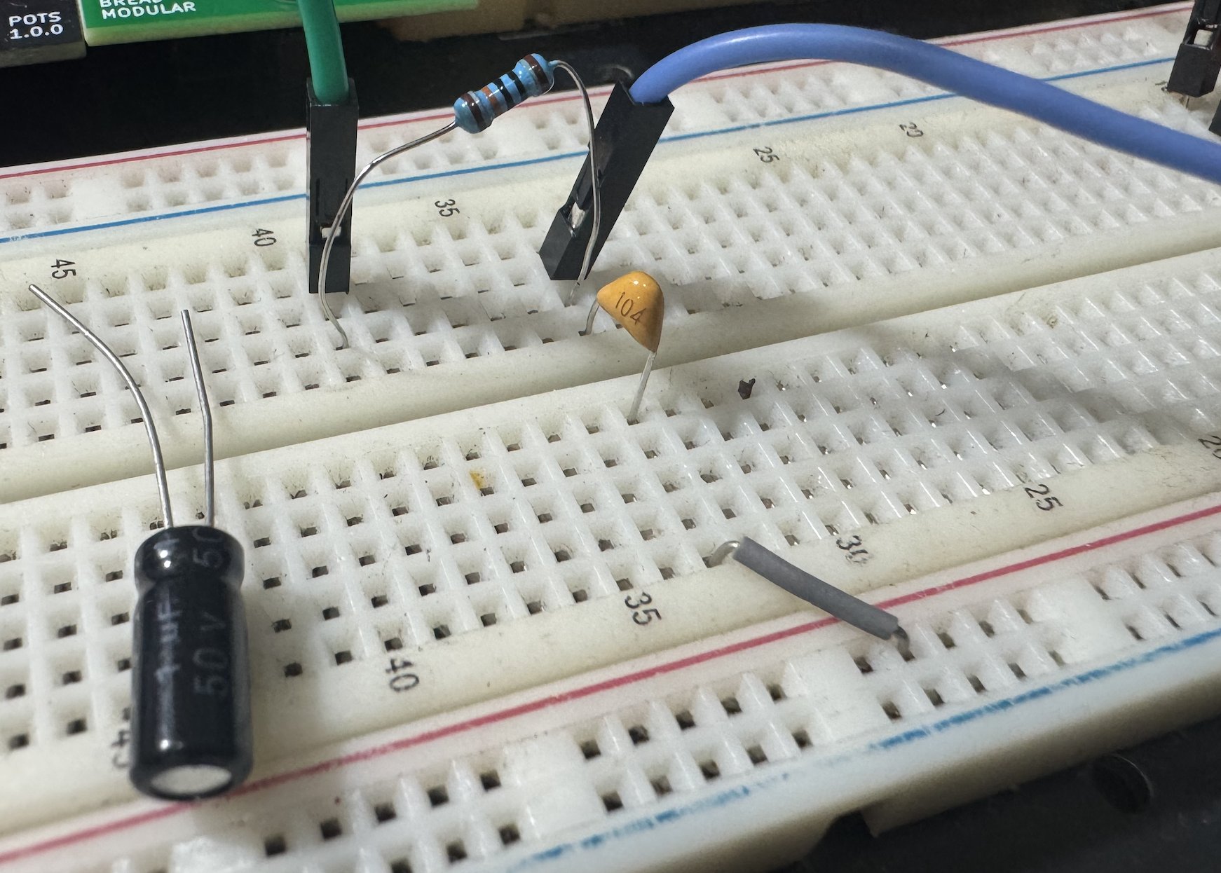
For 1µF and above, we use electrolytic capacitors. They are bigger, and the value is printed directly on them (like 1µF 50V).
🚨 Electrolytic capacitors have polarity, just like an LED. The stripe marks the "-" leg, which is also the shorter one. Ceramic capacitors (102, 103, 104) have no polarity, so you can connect them either way.
1. Charging a Capacitor
Let's see a capacitor in action. We feed a pulse into a resistor and a capacitor as shown below:
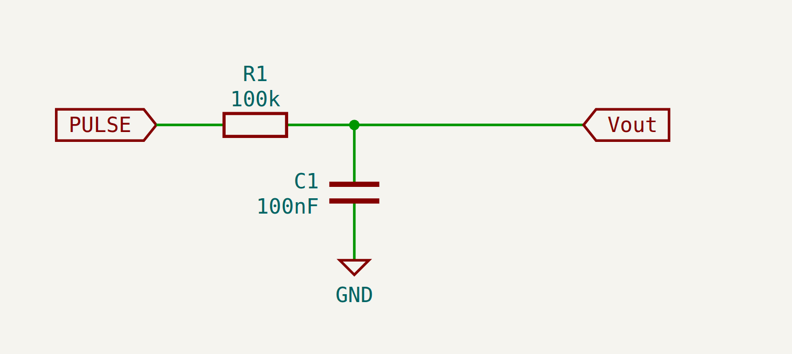
- Use the 16bit's G1 output (the pulse generator) as the PULSE.
- Set the pulse frequency to about 4Hz with the second potentiometer (CV2) of the 16bit. At this speed, you will get the same results as the scope captures below.
- Use a 104 (100nF) ceramic capacitor for C1.
- Connect the oscilloscope probe (the buffered probe from the previous course) to Vout.
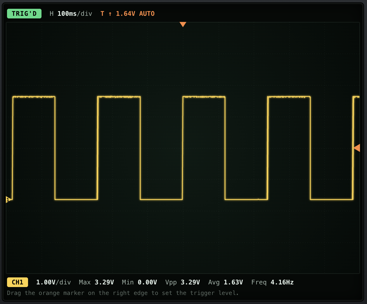
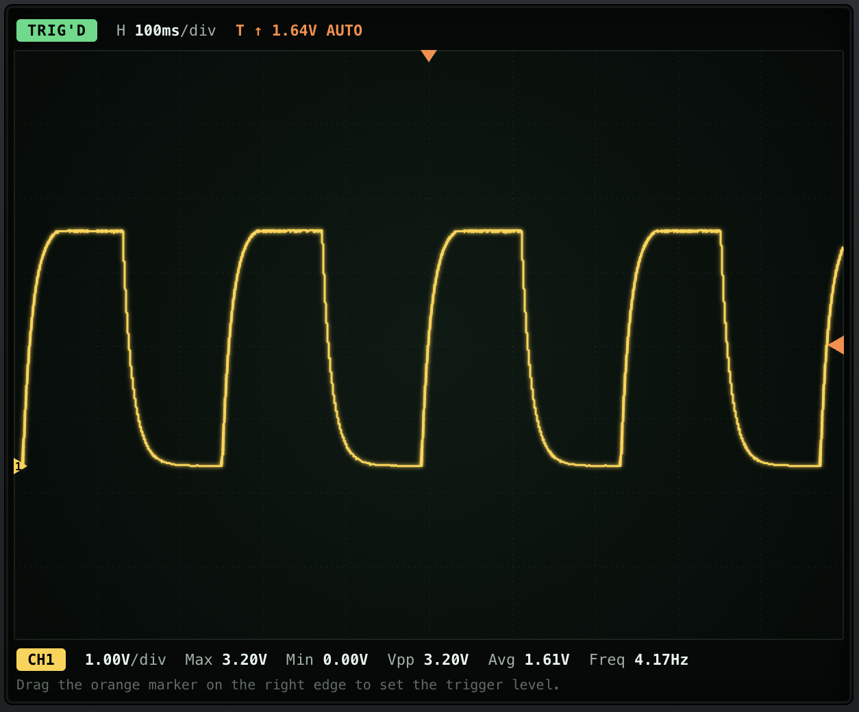
Instead of a sharp edge, we get a curve. When the pulse goes high, current flows through the resistor and fills the capacitor slowly. When the pulse goes low, the capacitor empties back through the same resistor.
💡 Does this look familiar? It's very similar to what we saw with the Vactrol in the previous course. The Vactrol is slow because of the LDR. Here, it's slow because of the capacitor.
2. The RC Time Constant
How slow? That depends on both R and C. We multiply them to get the time constant (τ, the Greek letter "tau"):
τ = R × C
For our circuit: 100k × 100nF = 100,000 × 0.0000001 = 0.01s (10ms).
Here's a rule of thumb:
- After 1τ, the capacitor is charged to about 63% of the input.
- After 5τ, it's practically full (more than 99%).
At 4Hz, the pulse stays high for about 125ms. That's way more than 5τ (50ms), so the capacitor has enough time to fill up and empty completely. That's why the curve reaches the top and the bottom.
Now replace the 104 with the 1µF electrolytic capacitor. Connect its "-" leg to GND. The time constant is now 100k × 1µF = 0.1s (100ms).
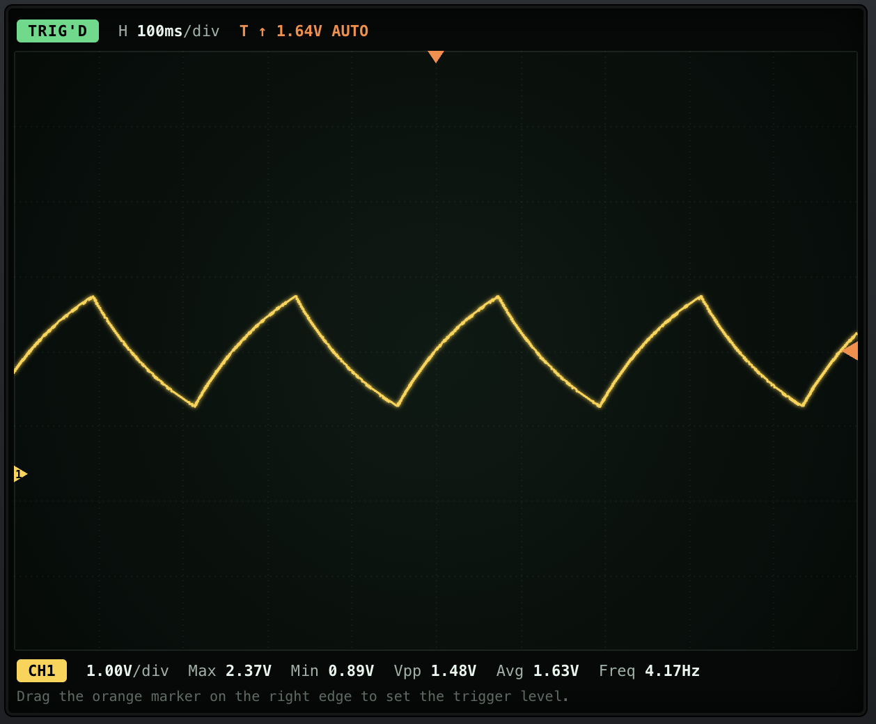
The pulse is still 4Hz, but 125ms isn't enough to fill a capacitor with a 100ms time constant. It charges a bit, then the pulse goes low and it starts emptying again.
🛠 Try the following and see how the curve changes:
- Replace the 100k resistor with 10k (with the 1µF capacitor). The time constant is now 10ms again.
- Go back to the 104 and increase the pulse frequency until the capacitor doesn't have enough time to fully charge.
This is important. A fast-changing signal gets smoothed and gets smaller. A slow-changing signal passes through almost as it is.
That's literally a low pass filter. We will build one in the next lesson.