
Lesson 4 of 6
Cascading Filters
A first-order RC filter is gentle (6dB/octave). To get a filter that sounds more "filtered", we can stack two of them. This is called cascading, and the result is a second-order or 12dB/octave filter.
💡 Each stage halves the signal for every octave above fc. Two stages halve it twice, so we get a quarter (-12dB) per octave.
1. Cascading Without a Buffer
Let's try the obvious way first. Just connect two RC filters back to back:
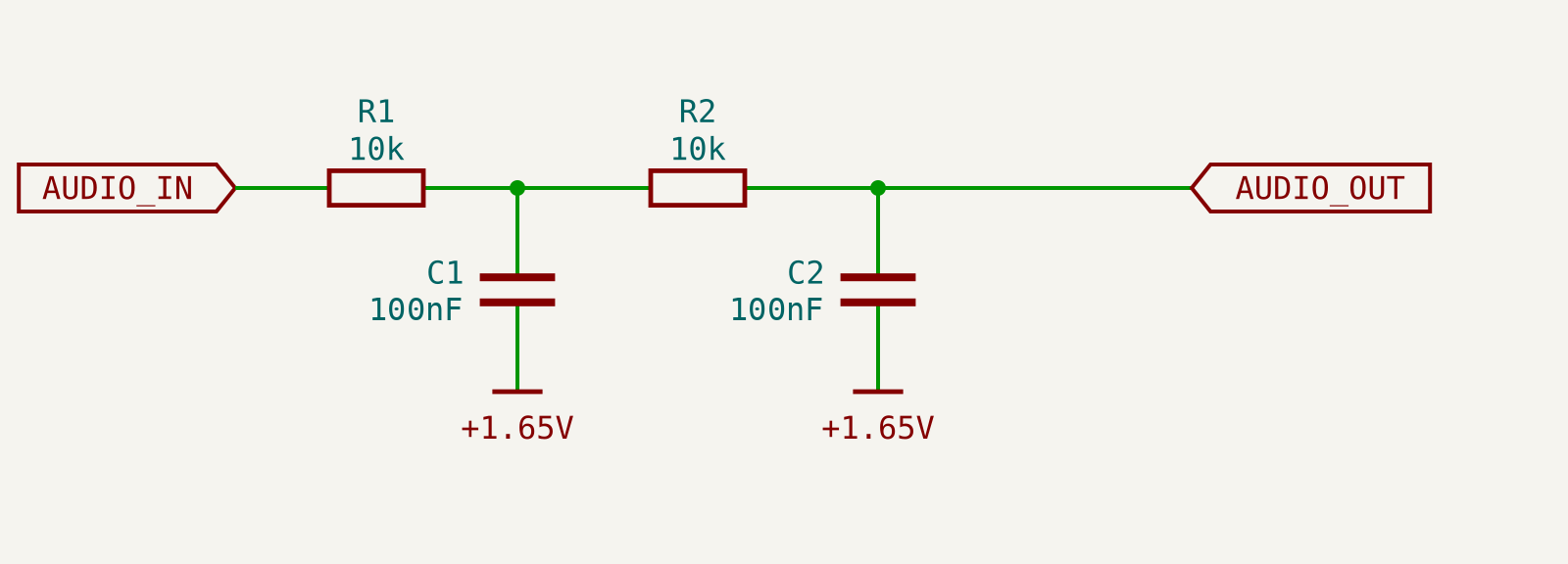
We use 10k and 100nF for both stages (fc ≈ 160Hz), so the effect is easy to see on the scope. Connect the scope just like in the previous lessons:
- The audio input goes to the 16bit's A2 input (blue).
- The probe goes to the 16bit's A1 input through the buffered oscilloscope probe (yellow).
Now probe the middle point (C1) with and without the second stage connected.
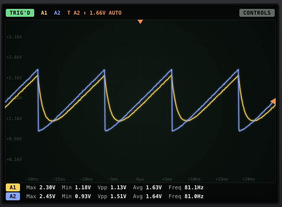
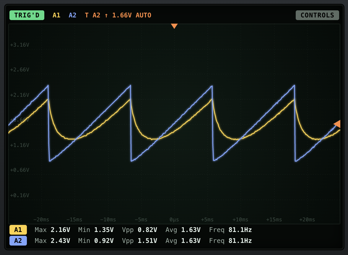
The first stage changes as soon as we connect the second one. It's the same loading effect we saw with voltage dividers. The second stage draws current from the first stage's capacitor, so the first filter is no longer a 160Hz filter. It filters more than it should, and the signal gets smaller.
💡 You can fix this with the 10X rule. Make the second stage's R 10X bigger and C 10X smaller (100k and 10nF). The cutoff frequency stays the same (~160Hz), but the second stage now loads the first stage 10X less.
This trick was used a lot in old designs. But we have a better tool now.
2. Cascading With Buffers
Put a buffer after each stage:
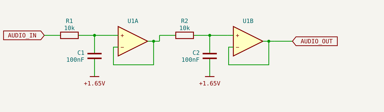
- U1A has very high input impedance, so it doesn't load C1 at all.
- U1A's output impedance is 0 ohms, so the second stage sees a perfect source.
- U1B does the same for the output.
Now both stages are exactly the same and work independently. No calculations needed.
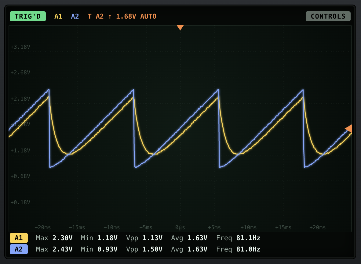
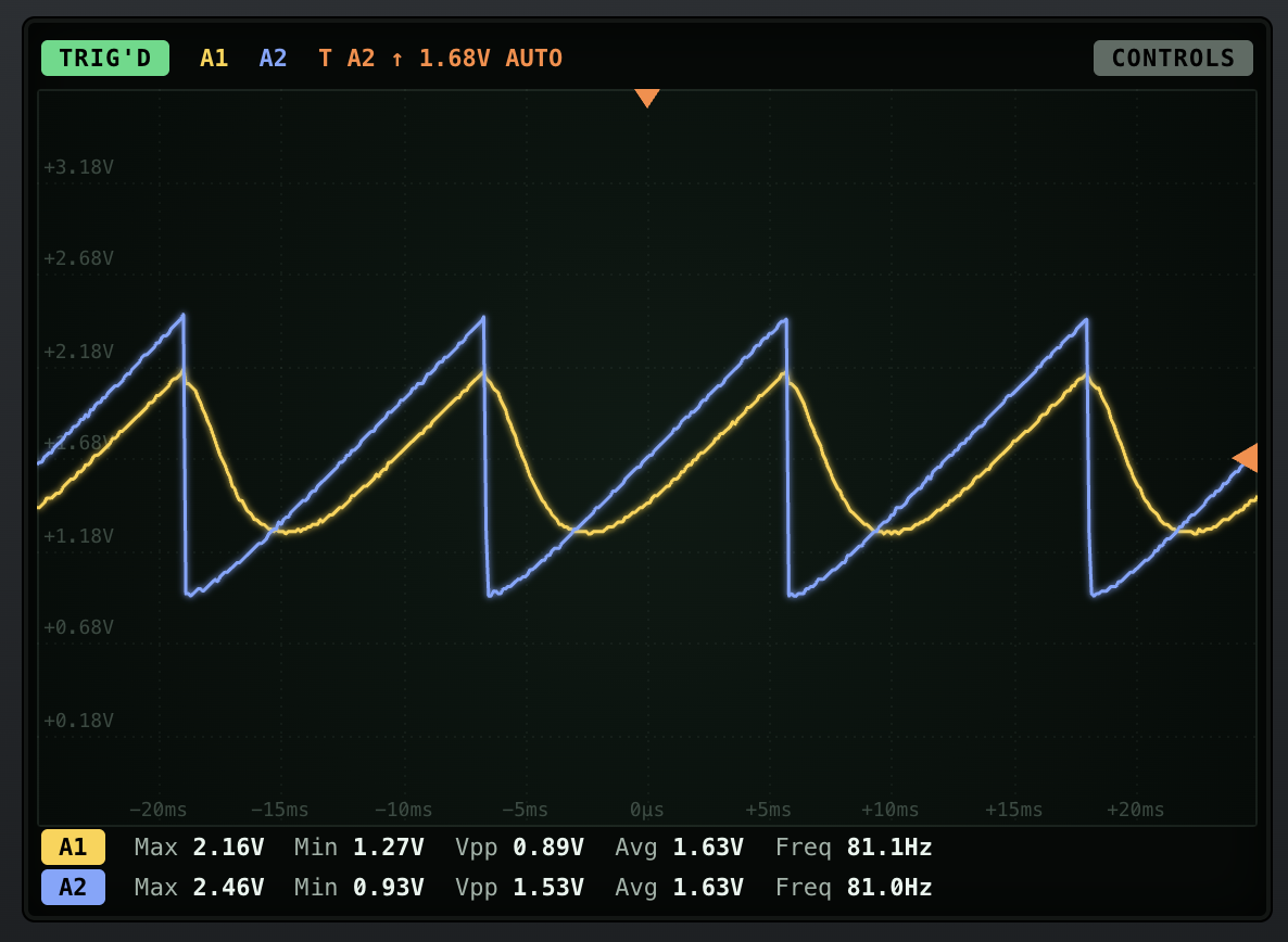
👂 Switch the line out between the first stage and the second stage. The second stage sounds noticeably darker, even though both stages have the same cutoff frequency.
🛠 Feed the 16bit's A2 output (super-saw) and try different resistor values for both stages. Always use the same value in both stages.
3. Look at the LOW Module
Now have a look at the core of the LOW module:
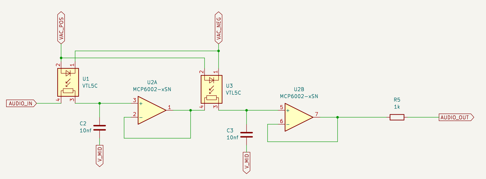
Can you see it? It's exactly what we just built:
- U1 + C2 is the first RC stage, and U2A buffers it.
- U3 + C3 is the second RC stage, and U2B buffers it.
- Both capacitors (10nF) go to V_MID, which is our 1.65V virtual ground.
- R5 sets the output impedance to 1k, like every Bread Modular output.
The only difference is the resistors. Instead of regular resistors, the LOW module uses the resistor side of two Vactrols (U1 and U3). That's how we control the cutoff frequency with a voltage. We will build that in the next lesson.