
Lesson 6 of 6
Building the Low Pass Gate
Okay. Now we have all the tools to build the LOW module. Check out the following diagram. You will find familiar sections.
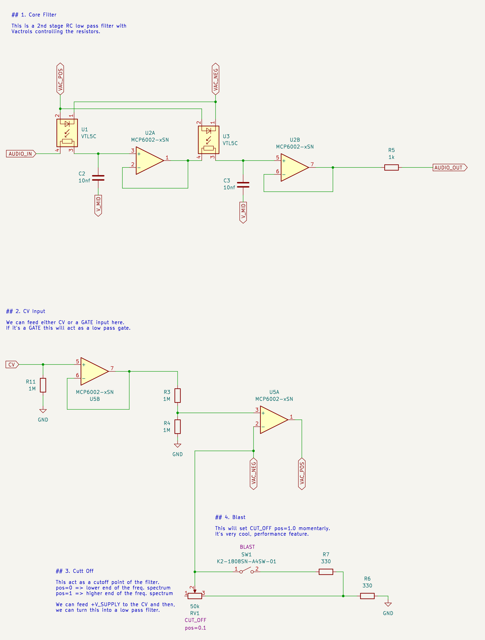
Let me walk you through it:
1. Core Filter
- Two buffered RC low pass stages, just like in the 4th lesson.
- The resistor sides of the Vactrols (U1 and U3) are the R of each stage.
- Both capacitors (10nF) go to V_MID (1.65V, made with a 1k divider).
- R5 sets the output impedance to 1k.
2. CV Input
- U5B buffers the CV input, so the module never loads whatever drives it.
- R11 (1M) pulls the CV input to 0V when nothing is connected. So, the filter stays closed (silent) by default.
- R3 and R4 halve the CV for the current driver.
3. Cutoff
- U5A is the voltage-controlled current source from the previous lesson.
- RV1 (CUTOFF) and R6 set the current, which sets the maximum cutoff frequency.
4. Blast
- SW1 adds R7 in parallel with the CUTOFF pot and opens the filter instantly.
💡 There's also a "V+" pin in the LOW's input section. It's 3.3V through a 10k resistor (R12). You can patch it into the CV input to keep the filter open. The 10k resistor protects the supply if you accidentally patch it somewhere else.
Building It
You need 4 opamps (the whole opamp breakout), 2 Vactrols and two 10nF capacitors.
- Build the core filter on the top half of the breadboard. It's the same two-stage filter from the 4th lesson, with Vactrols in place of the resistors.
- Build the CV input and the current driver on the bottom half. It's the same driver from the previous lesson.
- Use the 50k pots module as the CUTOFF control.
- Use a jumper wire as the BLAST switch.
🚨 Double-check the Vactrol orientation before powering up. The LED side has polarity. If it's reversed, the filter stays closed no matter what CV you send.
1. As a Low Pass Filter
- Feed the 16bit's A2 output (super-saw) into the audio input.
- Connect 3.3V to the CV input.
- Turn the CUTOFF pot.
With 3.3V on the CV input, the Vactrols get a steady current. So, the LOW works as a normal low pass filter, and the CUTOFF pot sets its cutoff frequency.
- With the CUTOFF low, the super-saw loses its sharp edges and sounds dark and muffled.
- As you turn the CUTOFF up, the filter opens and the sound gets brighter.
- With the CUTOFF high, almost all the harmonics pass through and you hear the full super-saw.
🛠 Now touch the BLAST jumper wire (connect R7 to VAC_NEG) while the CUTOFF is low. The filter opens fully while you hold it.
2. As a Low Pass Gate
A Low Pass Gate (LPG) is a filter and a VCA at the same time. When the CV is 0V, the filter is so closed (below 2Hz) that no sound gets through, so it also acts like a VCA. As the CV rises, the sound gets louder and brighter at the same time, just like a real plucked or struck instrument.
- Connect the 16bit's G1 output (pulse) to the CV input.
- Set the pulse to a slow rate.
Now you'll hear a short "pluck" with every pulse:
- When the pulse goes high, the Vactrol LEDs turn on and the filter opens quickly. That's the sharp attack.
- When the pulse goes low, the sound doesn't stop right away. It fades out and gets darker at the same time.
- Between the pulses, the filter is fully closed and you hear nothing.
Listen to the decay. We never added an envelope generator, but the sound fades out smoothly. That's the Vactrol. Remember from the previous course: the Vactrol is slow to react, especially when it goes dark. That slow response acts as a built-in decay envelope.
💡 This is why Vactrol LPGs are famous for their "bongo" or "plucked" sound. It was made popular by Don Buchla in the 1970s, and it's still one of the most loved sounds in modular synthesis.
👂 The LOW works best with short gates. With a long gate, the filter just stays open. Try making the pulses as short as possible.
3. More Experiments
- Use the envelope generator as the CV. Try a fast attack with different decay times.
- Feed some real music through the line in and use the LOW as a "filter sweep" with the envelope.
- Change both 10nF capacitors to 100nF. The whole frequency range moves 10X lower. Better for deep bass?
- Remove the second stage (feed the U2A output to R5 directly). Compare the 6dB/octave and 12dB/octave versions.
- Replace R6 with a 1k resistor. How does it change the maximum cutoff frequency?
🎉 Yeah! Now you understand the complete LOW module, as we promised in the beginning. You can also build a LOW module yourself or get one for your Bread Modular system.